|
Collins Radio was the major innovator of the mechanical and crystal filters. These devices were designed so that their bandpass was much more effective than other passive
filters of the day (cuts QRM). The mechanical filter was a small compact unit with a series of dash pots (think of shock absorbers). The mechanical model could easily be converted to the electrical model of a
multisegment RLC (Resistor, Inductor, Capacitor) filter. That is exactly how they operated using the principal of "Magnetostriction". The advantages were lower insertion loss (signal attenuation) and very
sharp "skirts". This euphemism relates to how fast the attenuation occurs when the limits of the pass band are exceeded
(see figure 1.0). The crystal filters work in a similar manner except on a different principal. The crystal filters used the piezoelectric effect causing a deformation of the quartz block (when voltage is
applied the crystal warp). The crystal structure can be modeled into a RLC equivalent as well.. By being aware of the lattices structure and the physical size (by milling) these filters could be tuned to the desired
pass band response desired. The crystal filter was a evolutionary next step in design from the mechanical filter. These filters gave Collins a marketing edge in the communications industry and were used in both
Receivers and Transmitters. The following paragraphs give a simplistic description of their operation.
Receivers: The filters were designed (still are) to have a center frequency of the lower IF (typically 455 kHz or 500 kHz). In the Collins manufactured unit we see Filter model 455-J-2.1. In this case the center frequency is 455 kHz (middle of the IF bandpass) and
the package style is "J" (discussed later - plugs into the 75A-4) and the pass band is 2.1 kHz. In the ideal, only transmitted audio in the range of 0 Hz to 2100 Hz will be heard.
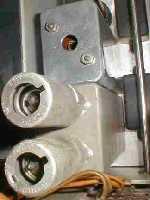
The advantage to the Collins filters is that they were closer to the ideal than the competitive systems (at the time). The picture to the left is of a OEM module plugged into a 75A-1.
Transmitters: The filters were designed to have a center frequency of the IF and the output is mixed with the carrier in the ring modulator ( also suppressed the carrier
frequency). The filter pass band was adjusted to allow the pass band (2.1 kHz) for upper or lower sideband by
switching the center of the IF bandpass (switching the local oscillator). The desired result is all of the transmitted power resides in the upper or lower 2.1 kHz of the selected sideband as passed by the filter.
|

